
Back in June 2025 we wrote Beautiful but not quite there yet. We’d been trying text-to-CAD tools (Meshy, AdamCAD, ChatGPT) to design a printed headlight pod with a brake duct. We got great looking renders. We didn’t get accurate surfaces or a model we could actually change. The part on the car ended up being a bent piece of aluminum, some hose clamps and epoxy.
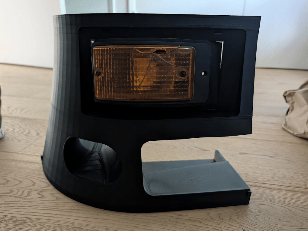
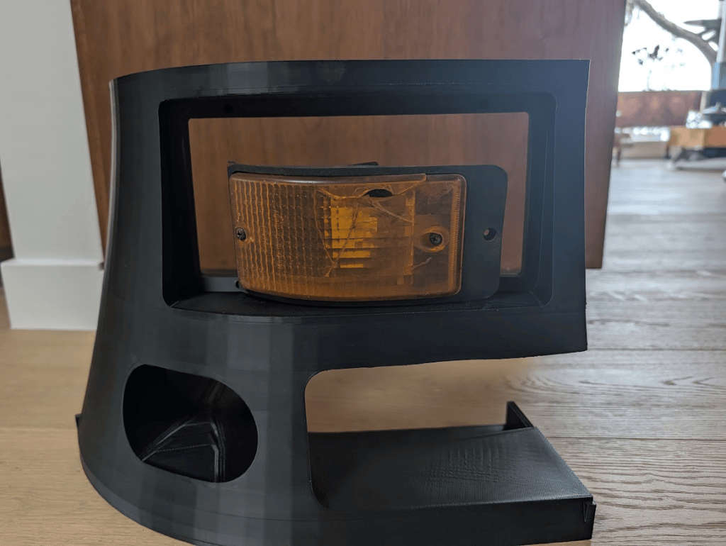
17 months later, the first segment of the printed GT bumper for the 924S is off the printer. Same design workflow as in the last post, almost entirely Claude, and this time the stock turn signal drops into the pocket it was designed for.

o o o
WHAT CHANGED
| June 2025 | November 2026 | |
|---|---|---|
| Input | Text prompts | A few photos, the stock mount points, plain-language notes |
| Output | A render / mesh | Print-ready STL straight to the slicer. Parametric OpenSCAD only when it’s worth it |
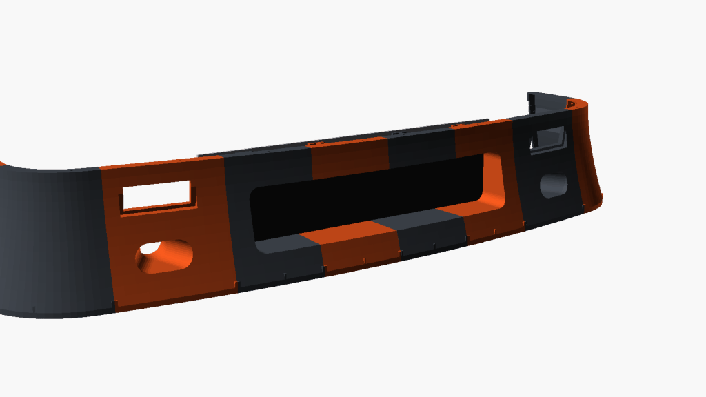
| Printability | Hope | Split into bed-sized segments, bolted + doweled joints |
| Documentation | None | Drawing with elevation, section, plan and build notes |
| Unknowns | Hidden under a nice surface | Flagged as PLACEHOLDER, “NOT VERIFIED ON CAR” |
| Feedback | Rephrase and try again | Point out the problem, fixed in minutes with the reasoning |
Last time I wondered if sketches or marked-up photos would be the way to give feedback. Turns out photos plus talking it through like you would with an engineer was enough. No sketching needed.
o o o
IT EVEN MAKES DRAWINGS
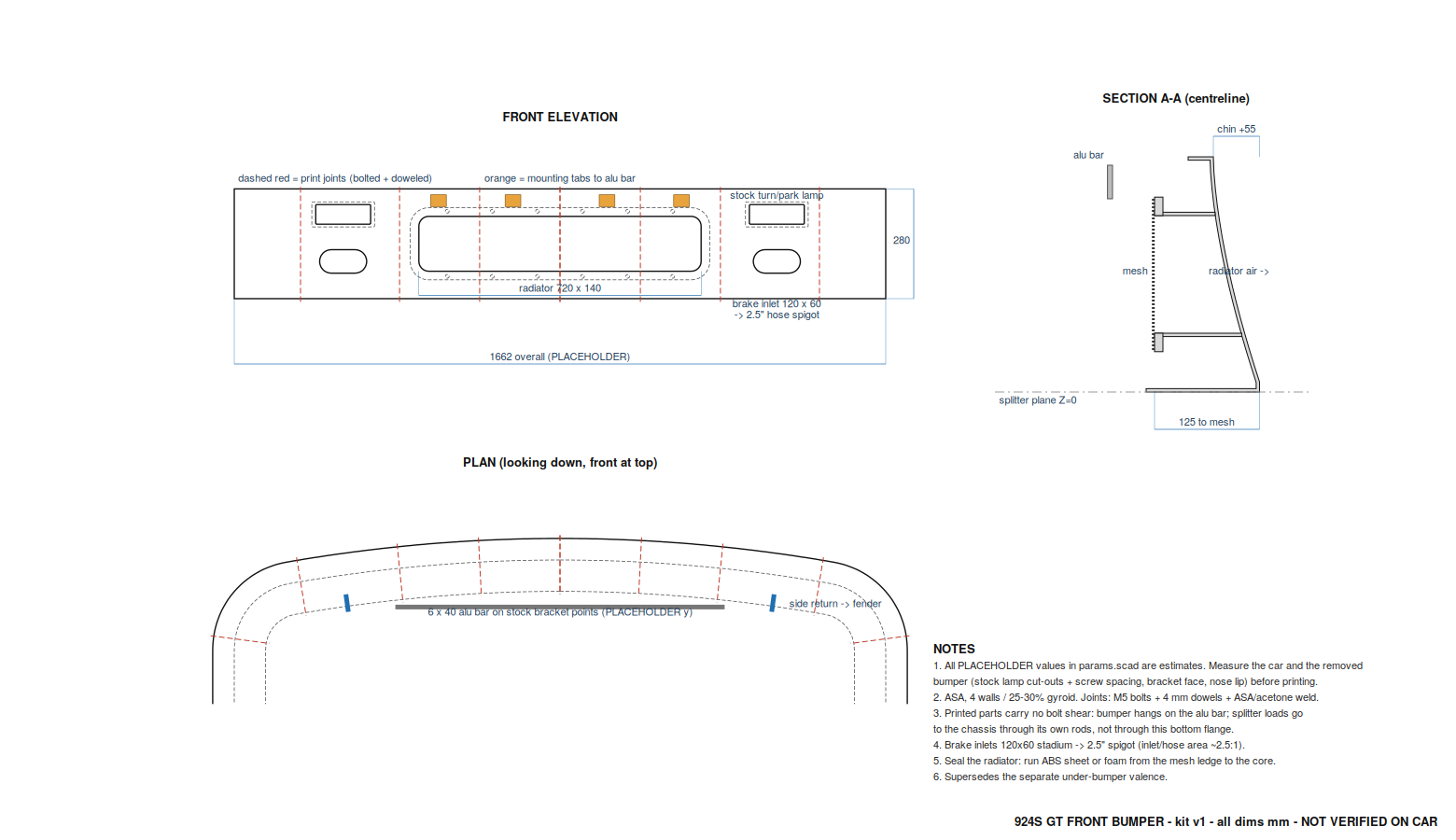
A few things in the notes I didn’t ask for but liked:
- Brake inlets are 120 × 60 mm stadiums feeding a 2.5″ hose, roughly 2.5:1 inlet to hose area
- Printed parts carry no bolt shear. The bumper hangs on an aluminum bar on the stock bracket points, and the splitter loads go to the chassis through its own rods
- ASA, 4 walls, 25-30% gyroid. Joints are M5 bolts, 4 mm dowels and an ASA/acetone weld
o o o
FIRST CORNER
We started with the hardest piece. The corner carries a whole turn signal and a whole brake duct inlet, and only fits the printer bed turned at an angle.
o o o
NOT QUITE THERE (STILL)
We deliberately started with just a few reference measurements, to see how far photos alone would get us. Pretty far. But some key numbers, like the overall width and where the stock brackets sit, are still estimates, and the drawing says so in big letters.
Next iteration gets a bit more prep: more photos with key measurements in them before building. That should cut the number of iterations and the time further.
For this bumper, next is a test fit, then printing the rest. After that, the lightweight single-piece version with Swellcycle.

